
Bridget Manual
Overview
The SGF Devices™ Bridget is a high performance low cost stickless controller based on the Flatbox rev 4 by jfedor2 (https://github.com/jfedor2/flatbox). It runs the GP2040-CE firmware (https://gp2040-ce.info/) and is compatible with PS3, Switch, and PC (Xinput or DirectInput). It comes pre-configured with all necessary firmware and SOCD cleaning.
Firmware updating is not recommended unless you need a new GP2040-CE feature. We never ship with firmware with any known issues, and updating firmware can introduce instability if done improperly or impact previous feature sets.
For questions about software configuration, firmware updates, and software support, please refer to the GP2040-CE documentation at https://gp2040-ce.info/#/usage
Layout
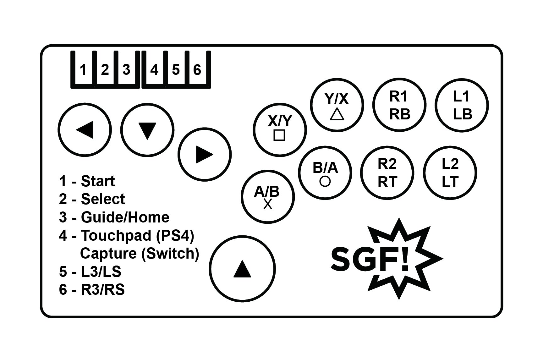
Changing Input Method (PC/Switch/PS3/PS4)
Using the layout as noted above, hold the following buttons while plugging in the controller to change the input method. Note: this is saved across plug/unplug cycles.
Cross - Switch
Circle - Xinput/PC
Square - DirectInput/PS3
Triangle - PS4
Changing Directional Behavior
Using the layout above, hold the following buttons at any time to change the directional input behavior. Note: this is saved across plug/unplug cycles.
BACK+START+LEFT - Left Analog Stick Emulation
BACK+START+RIGHT - Right Analog Stick Emulation
BACK+START+DOWN - Digital Dpad
Changing SOCD Modes
As of April 2023, the Bridget ships with Neutral SOCD as the default setting (U+D=none). Other settings can be chosen in the web config or with the following key combinations. Note: this is saved across plug/unplug cycles.
START+GUIDE+UP - Up Priority (U+D = U)
START+GUIDE+DOWN - Neutral (U+D = none, default)
START+GUIDE+LEFT - Last Input Priority (most recently pressed input is active)
Shell Disassembly
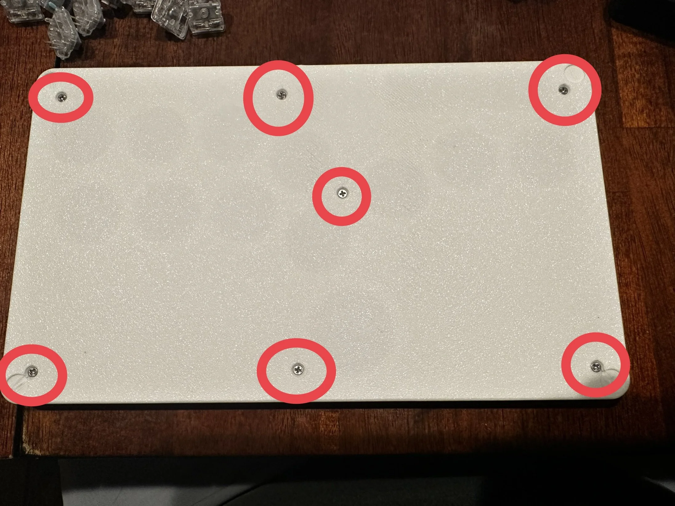
Before starting, unplug the device. To open the shell, remove the 7 screws from the back of the device, then lift away the back cover.
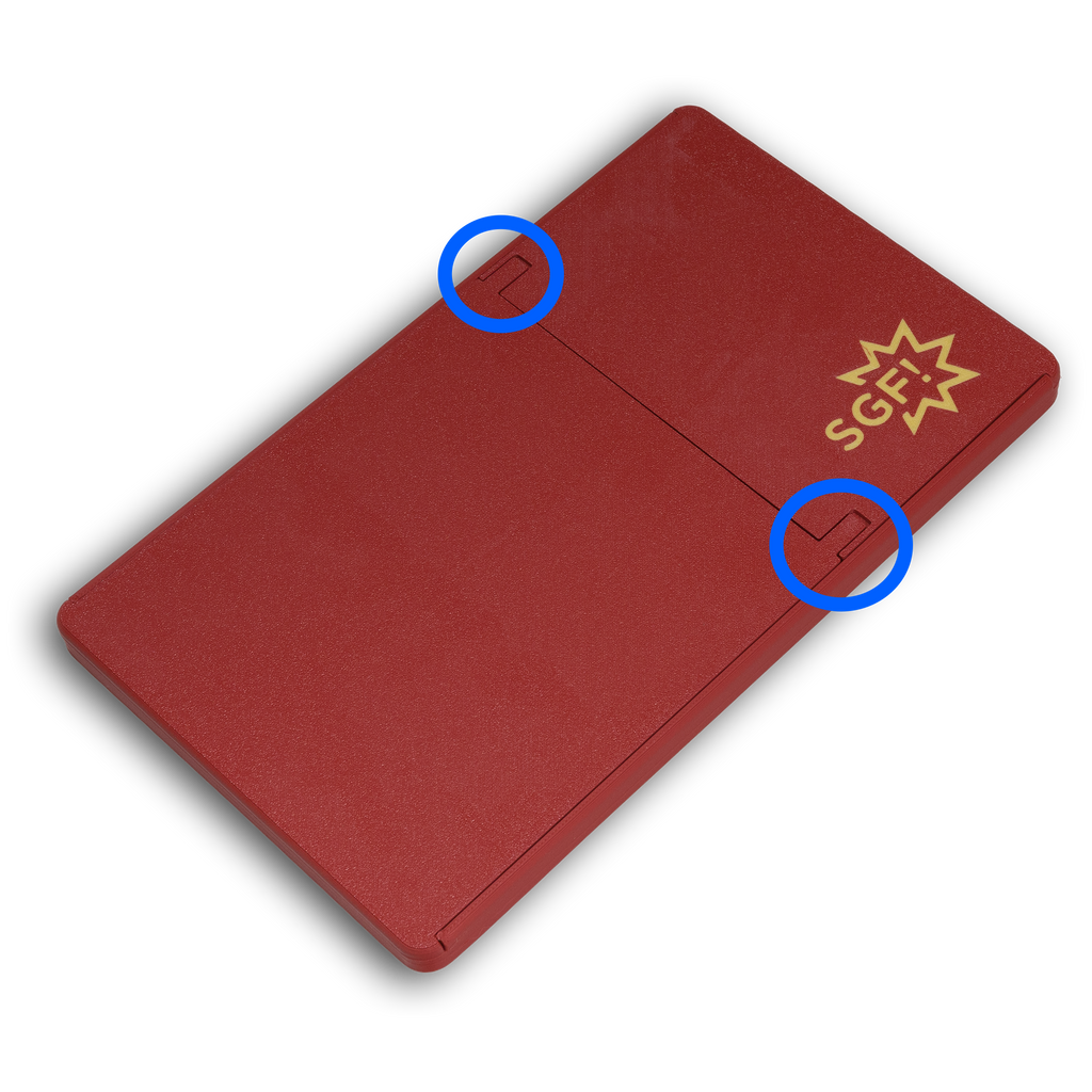
If you have a case without screws, lift up on the two tabs while pulling the two halves apart.

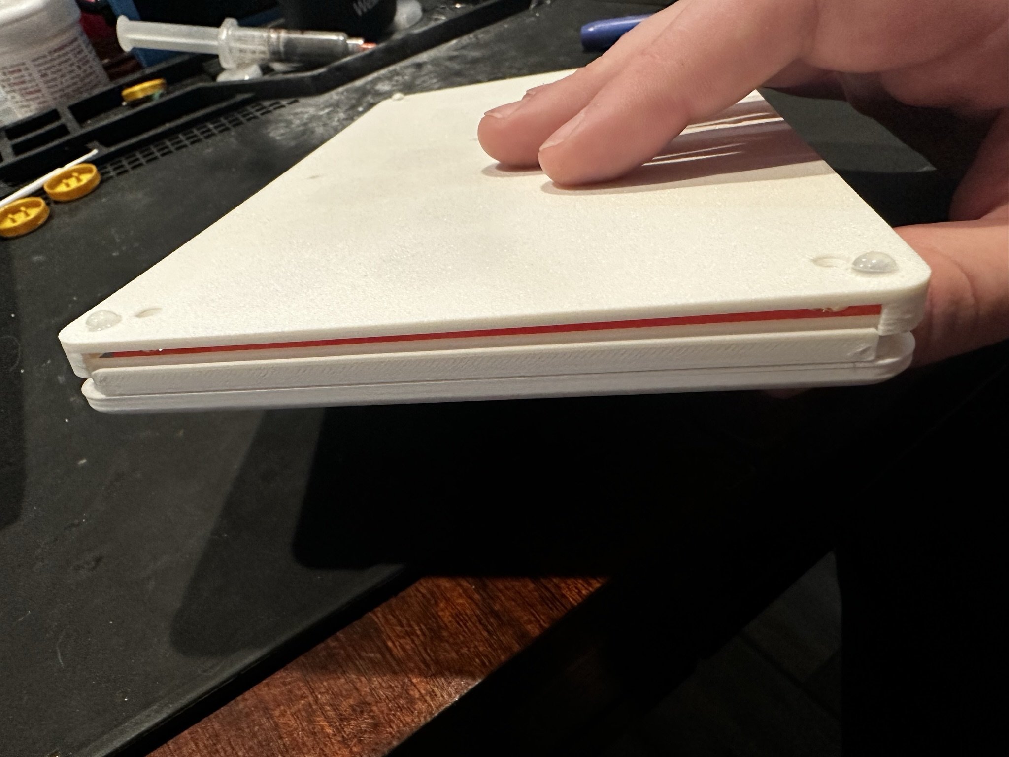
NOTE: If you have a newer revision of the shell, you will see small side plates on the left and right side of the controller as shown below. Take care not to lose these plates. They are retained by friction between the top and bottom shells and may fall out.
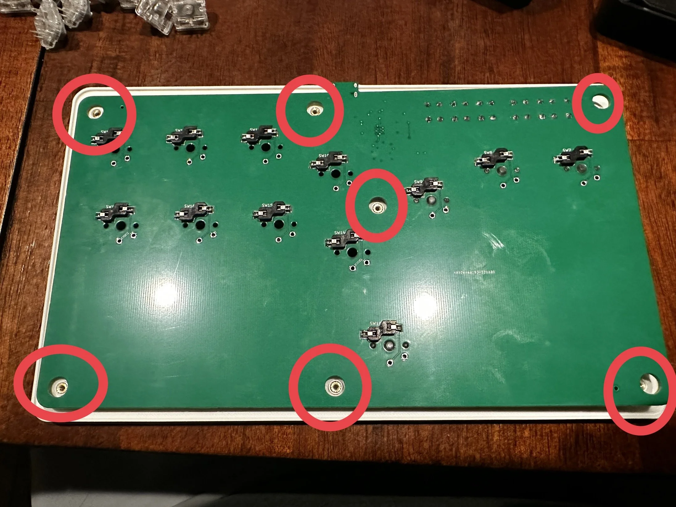
After removing the cover, gently remove the PCB from the locating posts. It may be snug, but don’t apply too much pressure.
Note: your PCB may be a different color, this is normal.
To reassemble the shell, carefully place the PCB onto the front shell in the correct orientation, and ensure the PCB is seated fully around the alignment pins. This may be a tight fit.
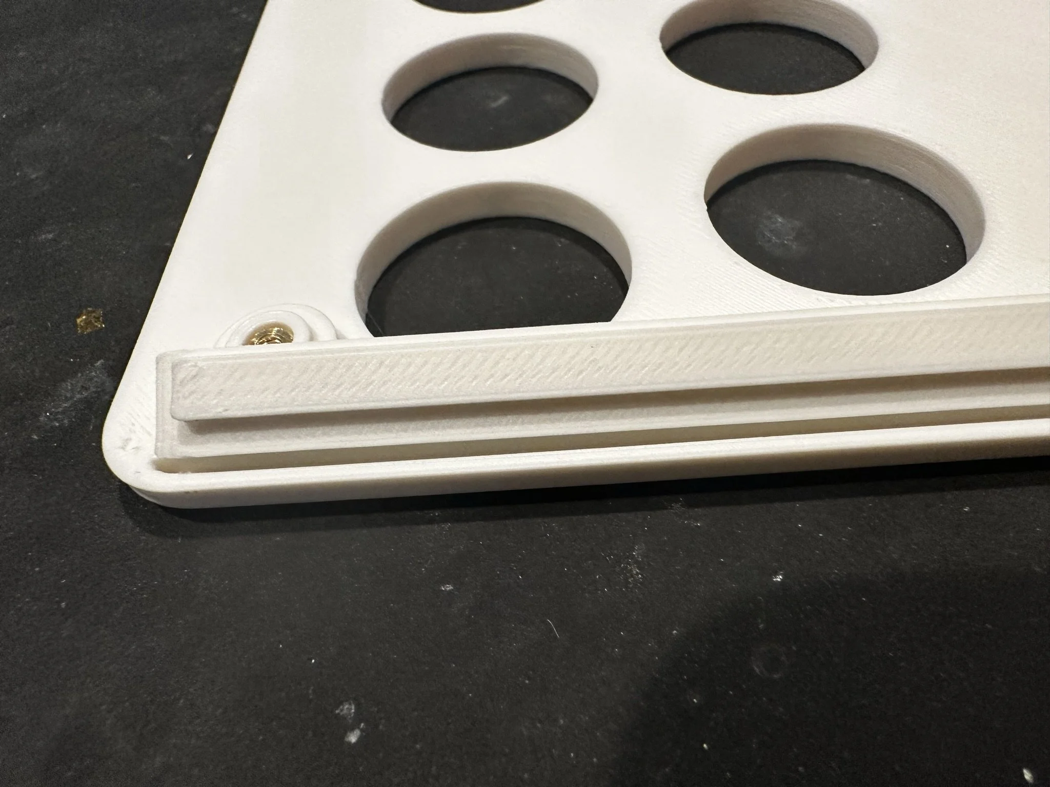
When reassembling, if you have the revised shell with side plates, insert the side plates in the top shell first. The side plate slots deeper into the top shell than the bottom, so make sure it is oriented as shown.
After checking alignment, place the back shell over the PCB and loosely install the screws. Ensure the side plates slot into the bottom shell if you have them. Then flip the controller over and press the buttons to ensure none are overlapping with the holes or getting pinched. If they are, re-align the PCB.
Once properly aligned, hold the shell and PCB together tightly while tightening the screws. Do not over-tighten the screws. They should be snug enough to hold the shell together firmly, but over-tightening can break the studs that retain them.
If you have a screwless case, carefully slide both sides into the rails that secure them and slide them together.

After fully seating the sides, press down on the tabs to be sure that they're fully engaged.
Removing Switches
Without Removing Shell
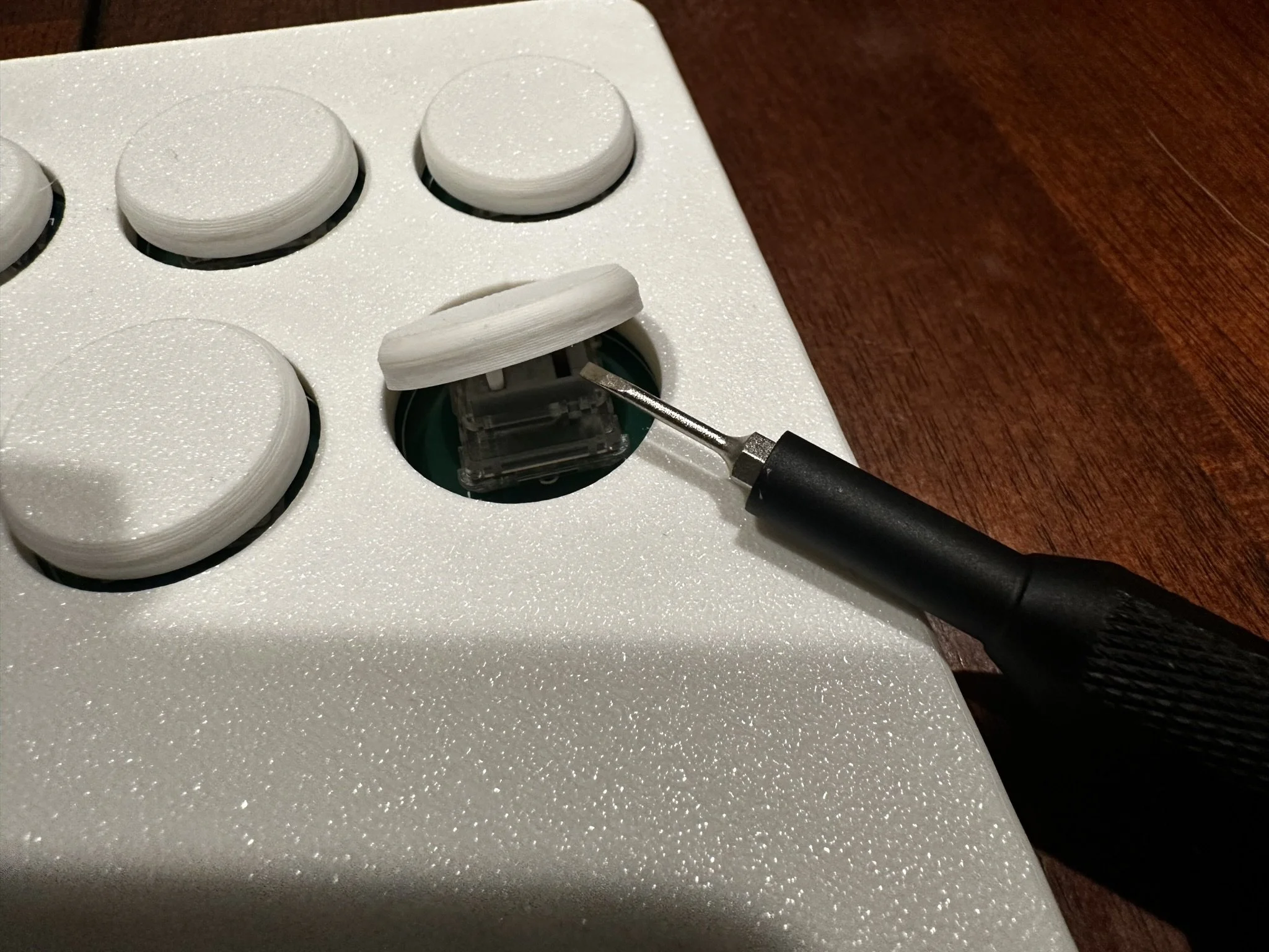
Insert a small flat screwdriver or similar tool under the button cap and pry it off. It may break off – this is okay, as replacement switches from us should include replacement button caps.
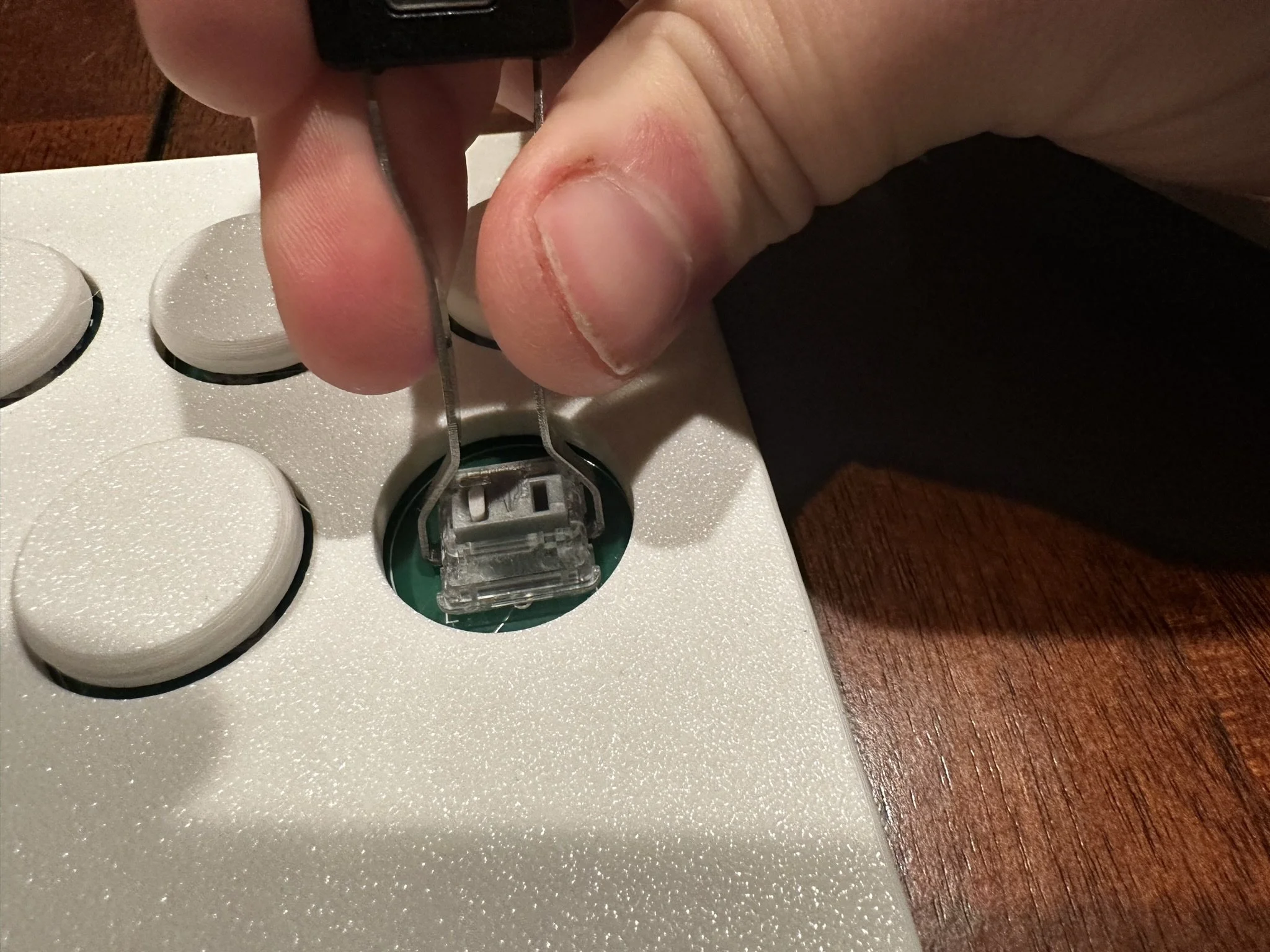
Remove the switch using a switch puller or a pair of pliers. Be careful not to damage the underlying PCB.
After Removing Shell
This method will not damage the button cap, and therefore can be more useful for cleaning or other scenarios where the button cap must be saved.
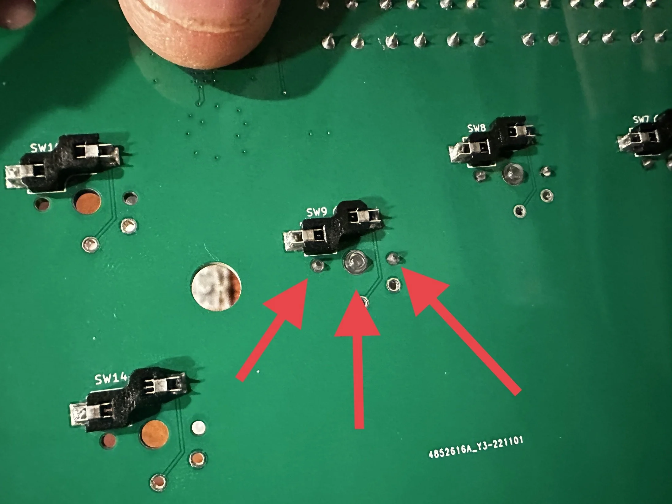
After removing the PCB from the shell, using a small blunt tool, push the 3 small retention buttons from the back of the PCB out towards the front. (These may be a different color than pictured). Newer revisions only have 1 retention button in the center.
This will loosen the button enough that it can be pulled away from the front side by hand.
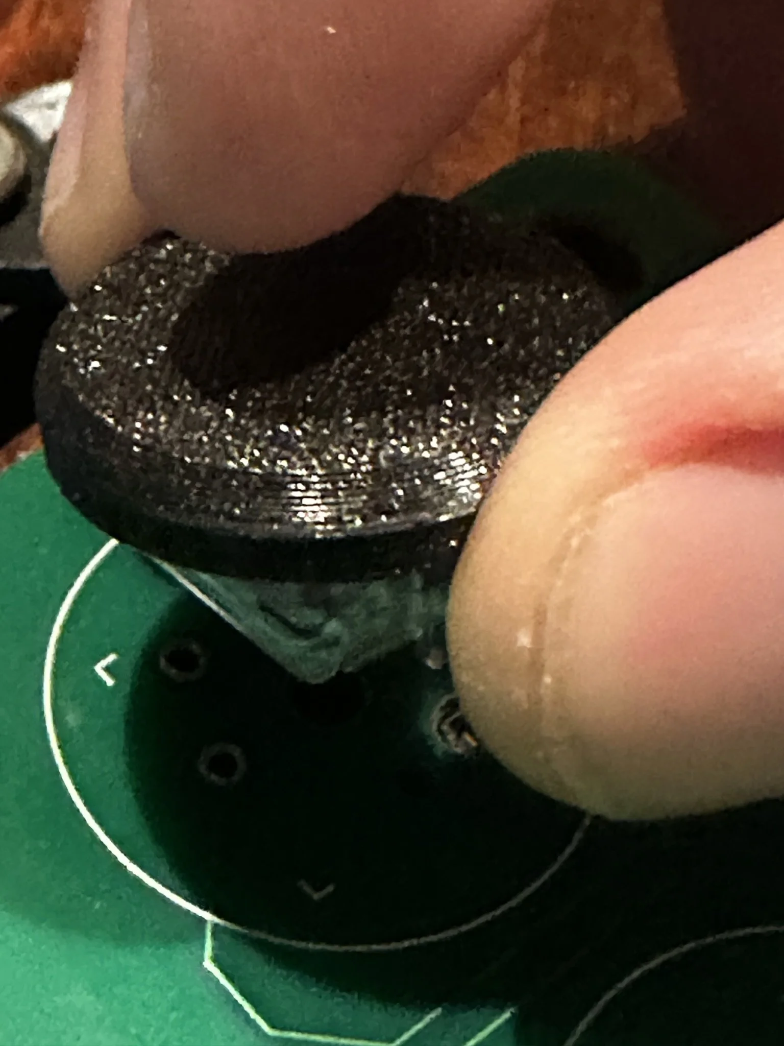
After removing the switch from the board, the button cap can be separated from the switch by gently pulling them apart with your fingers.
Installing Switches
This may be done with or without the shell on. Your replacement switches may or may not have button caps pre-installed. If they are not pre-installed, you may insert them into the switch before or after placing the switch on the PCB.
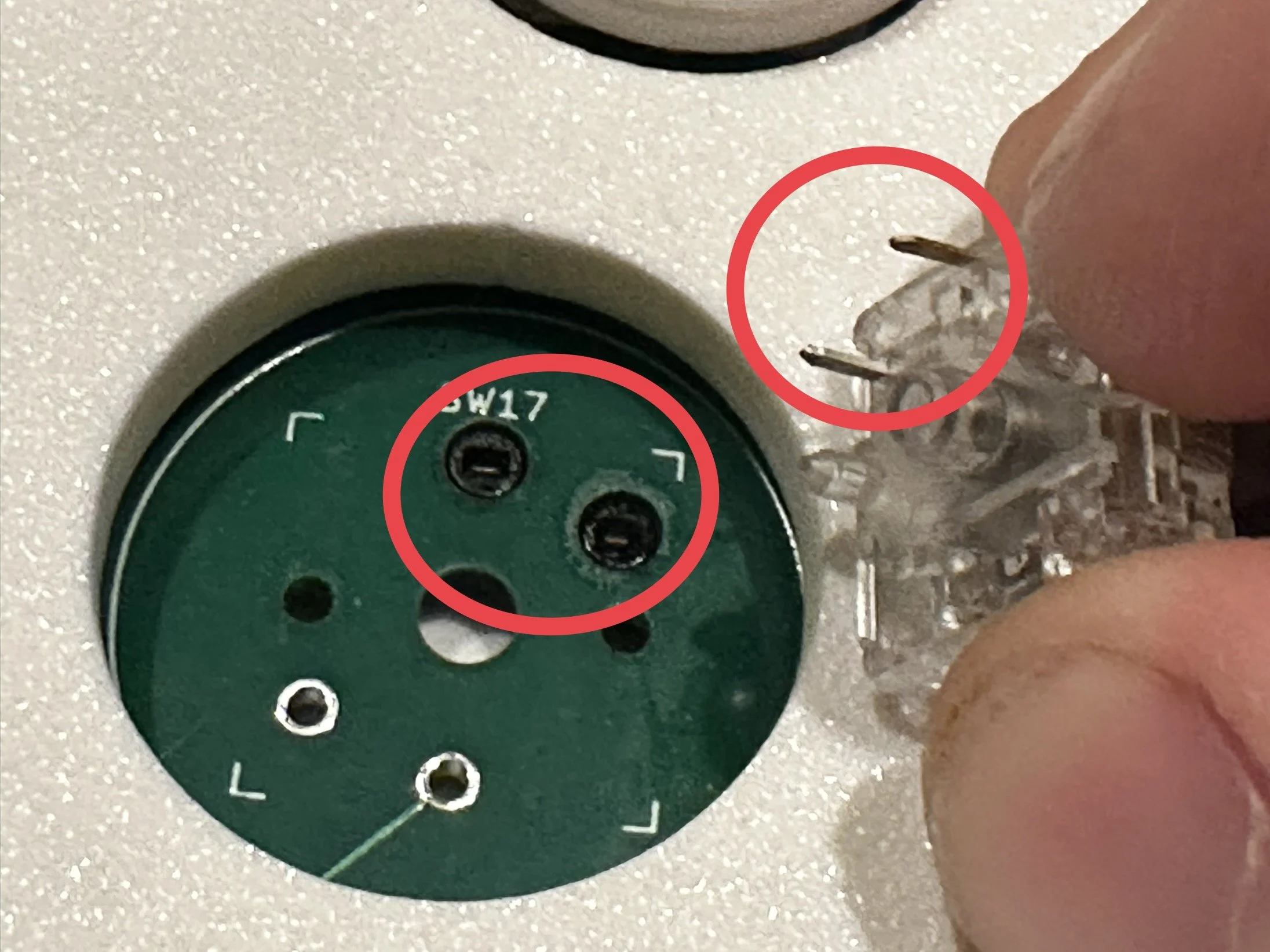
Ensure the two metal pins on the switch are aligned with the two black slots in the PCB, then press the switch onto the PCB firmly.
Note: Your PCB may look different. The black sockets are not always in the same spot.
If the button cap is not already installed, align the legs of the button cap in with the holes in the switch and press it in firmly. Newer switches use a cross-shaped alignment. In either case, just ensure the switch is aligned with the button cap. Tip: If you’re particularly firm while playing or the button feels a bit loose, you can add a very tiny drop of hot glue to the button legs for extra stability.
Configuration
The web configurator can be accessed by holding the START button while plugging in the controller to a PC, then navigating to http://192.168.7.1/ in a browser on the computer. Full reference for configuration options can be found at https://gp2040-ce.info/#/web-configurator. Note that changing values in the configurator may cause functionality issues. It is recommended to only adjust SOCD settings.